AI Server Power Consumption Soaring? IVS 50A (Supports Parallel) eFuse Solution
With the iterative development of AI and machine learning technologies, servers must simultaneously handle massive data processing and storage tasks, leading to persistently high system power consumption. A single server motherboard can reach a steady-state rated power of up to 5kW, while conventional general-purpose servers are typically rated at 1kW or 2kW. While keeping the device form factor unchanged, the continuous increase in power density presents numerous technical challenges for system design.
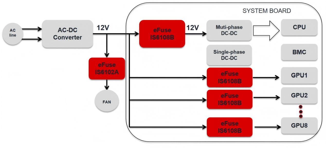
The diagram below shows a typical power distribution scenario in a 12V AI server. After input protection via a hot-swap circuit, power is distributed to downstream system loads.
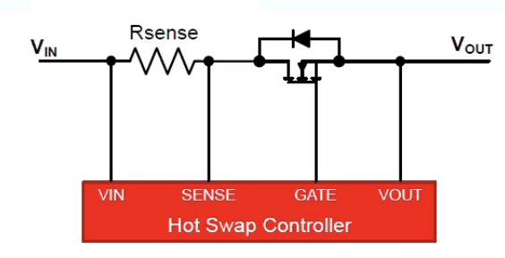
Reflecting on the evolution of hot-swap circuit architecture configurations over the years, the development characteristics are quite distinctive. Hot-swap solutions are primarily composed of three core components: an N-channel MOSFET serving as the main power control switch, a sense resistor for current detection, and a hot-swap controller.
As shown in the figure below, essentially, the hot-swap controller incorporates current and power limiting functions to restrict inrush and fault currents while ensuring the MOSFET always operates within the Safe Operating Area (SOA).
Traditional discrete hot-swap solutions have obvious shortcomings:
-
Large PCB footprint and numerous external components: Requires controllers, MOSFETs, sense resistors, diodes, TVS diodes, and many other components. The footprint is 2–3 times larger than that of an integrated eFuse solution, leading to high layout complexity.
-
Low protection accuracy and poor consistency: Due to temperature drift in sense resistors and op-amps, current detection errors can reach ±5% to ±10%. There is no built-in MOSFET over-temperature protection, making it easy to exceed the SOA operating range and requiring additional temperature measurement circuitry.
-
Slow response and weak fault isolation: Short-circuit response is on the order of μs to ms (eFuse is on the order of ns), which can easily damage MOSFETs or connectors.
Given the above shortcomings of traditional discrete solutions, the industry is increasingly adopting integrated hot-swap eFuses that incorporate a built-in MOSFET and use the on-resistance Rdson for current sensing. This approach effectively reduces the overall system footprint, significantly increases power density, and integrates multiple protection features such as current and temperature fault monitoring along with real-time monitoring.
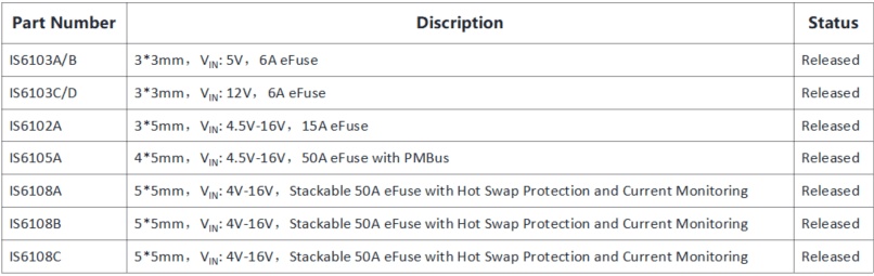
IVS hot-swap eFuse products offer output currents from 6A to 50A, support input voltages from 5.0V to 16V, and some models feature a PMBus interface and parallel operation capability, meeting the requirements of most data center applications.
Product Introduction (taking IS6108B as an example)
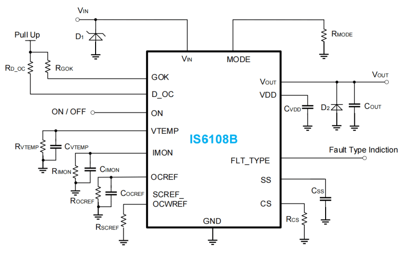
The IS6108B is an integrated hot-swap protection IC with a built-in 0.8mΩ MOSFET, used for fault protection such as overvoltage and overcurrent. The current limit protection value can be flexibly set via a resistor between the OCREF pin and GND. This IC integrates a current sensing circuit and provides an analog current monitoring signal. To limit the inrush current during power-on of the downstream load, an external capacitor can be connected between the SS pin and GND to set the output soft-start time.
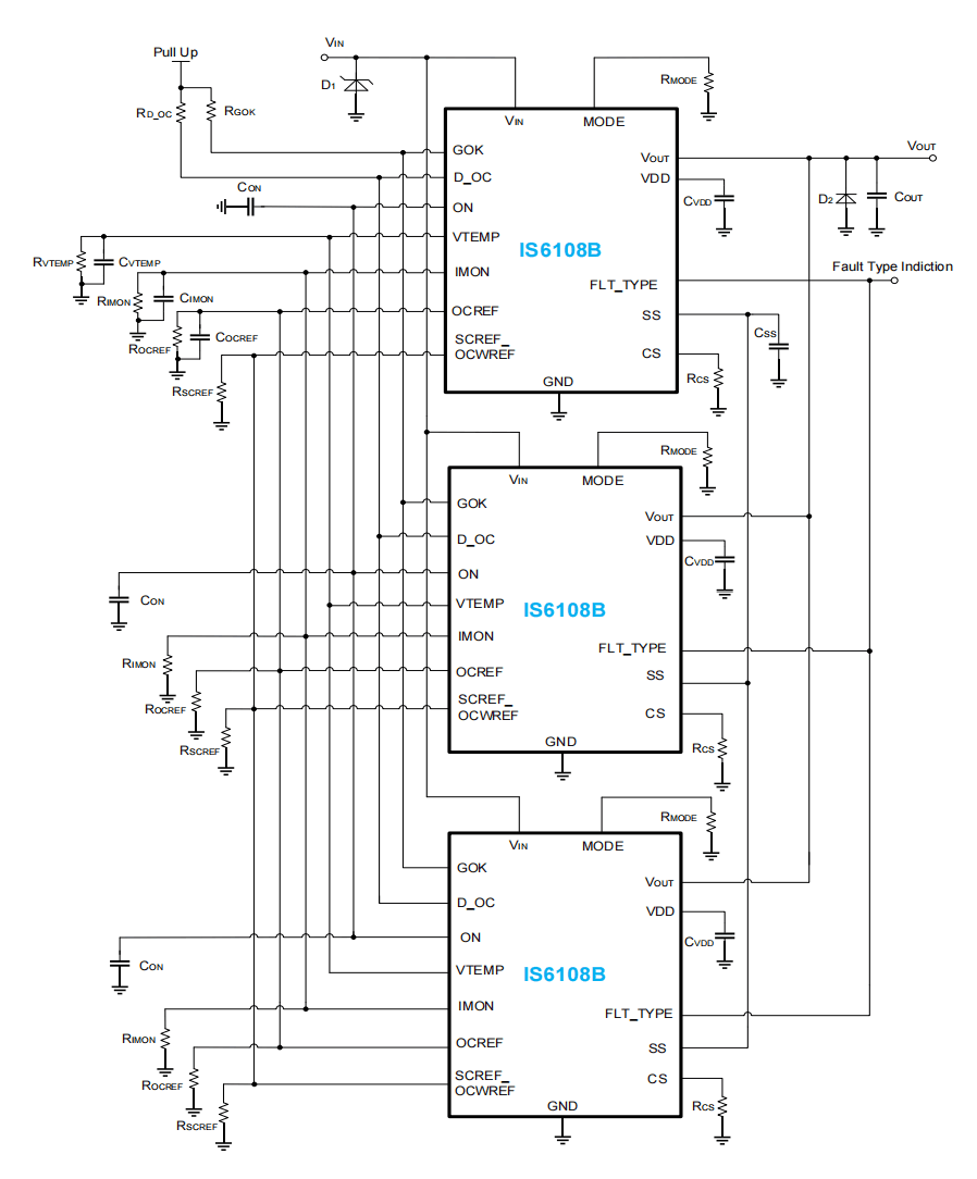
The IS6108B supports providing fault indication (GOK) and fault type (FLT_TYPE) signals to the system, facilitating system status monitoring and fault diagnosis. Additionally, the IS6108B supports multi-chip parallel connection for higher current applications. During the soft-start period in parallel operation, active current sharing between chips ensures balanced load current distribution.
Product Features:
- Wide input voltage range: 4V-16V
- Built-in 0.8mΩ MOSFET
- Precise current sensing: ±2%
- Adjustable soft-start time
- Adjustable overcurrent protection (OCP) and short-circuit protection (SCP) thresholds
- Fast short-circuit protection response time (typically 200ns)
- Fault indication and fault type output
- Supports parallel operation for higher current applications
- Active current sharing function during soft-start in parallel applications
Typical Applications:
Single-channel application block diagram:
Parallel application block diagram:
Key Feature Introduction:
-
Active Current Sharing During Soft-Start
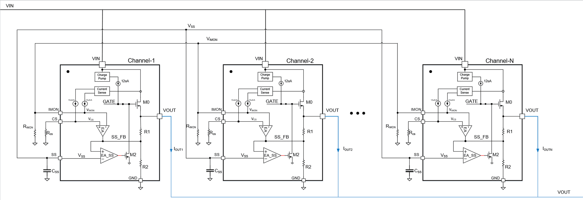
The figure above shows a typical application and internal block diagram:
-
When the output current of Channel 2 (IOUT2) is greater than that of Channel 1 (IOUT1), the corresponding single-phase sampling voltages satisfy VCS2 > VCS1.
-
Since all IMON pins of all phases are shorted together, VIMON corresponds to the average voltage of the total output current IOUT of N phases (i.e., VIMON corresponds to IOUT/N). Thus, the voltage relationship VCS2 > VIMON > VCS1 is formed.
-
The error amplifier (EA) adjusts based on the difference between VCSx and VIMON:
- Channel 2: EA output rises → VSS_FB2 voltage increases → M2 gate voltage rises → GATE2 drive signal weakens → IOUT2 decreases.
- Channel 1: EA output drops → VSS_FB1 voltage decreases → M2 gate voltage drops → GATE1 drive signal strengthens → IOUT1 increases.
-
This adjustment process continues until the output currents of all phases become consistent, achieving balanced N-phase current control.
-
-
Power Limit Function Introduction:
The IS6108B uses monolithic integration technology, placing multiple temperature sensors within the power transistor area. The controller can quickly sense temperature changes of the MOSFET in different regions and achieve reliable protection via OTP. Since power loss ultimately translates into device temperature rise, OTP can monitor the chip junction temperature in real time, serving as the core basis for power limiting and the final protection measure.
The Power Limit setting value of the IS6108B is 300W. When VIN=16V, Ids=300W/16V=16.875A. This can be understood as SS OCP = 16.875A.
Note: eFuses packaged in MCM (Multi-Chip Module) have an insulation layer between the temperature sensor and the MOSFET, so they cannot quickly sense MOSFET temperature and it is difficult to place multiple temperature sensors. Therefore, they can only rely on SS OCP for protection.
Test Results Demonstration:
-
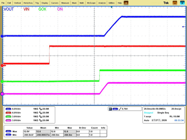
Hot-plug Test: The chip has a built-in insertion delay function that delays the power-on startup, avoiding voltage fluctuations during insertion. After the insertion delay ends, VOUT enters the soft-start process, effectively preventing overvoltage breakdown of downstream devices caused by unstable voltages during insertion.
-
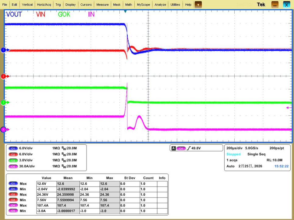
SCP Test: For a rapid high-current load on the output, the IS6108B immediately triggers SCP protection, responding within 200ns and turning off the FET. At this time, the FLT_TYPE voltage is 1.5V, indicating that the chip has triggered SCP protection.
-
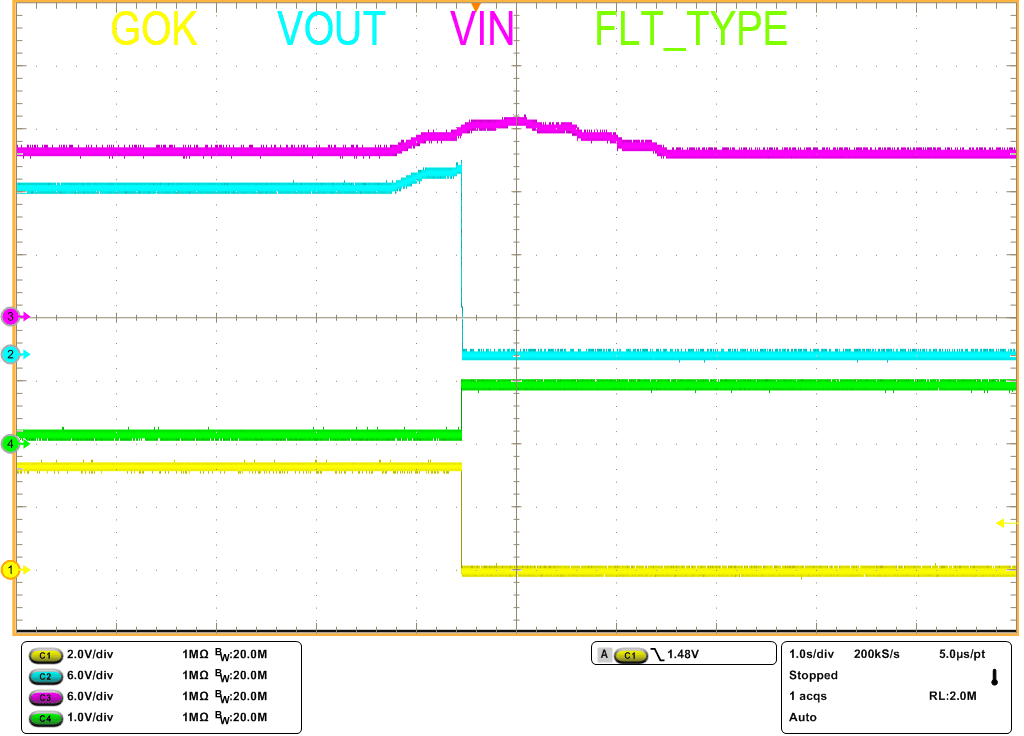
VIN OV Protection Function Test: When the system power supply voltage abnormally rises, the IS6108B can use VIN_OV protection to shut down the downstream circuit, ensuring the safety of the downstream circuitry.
-
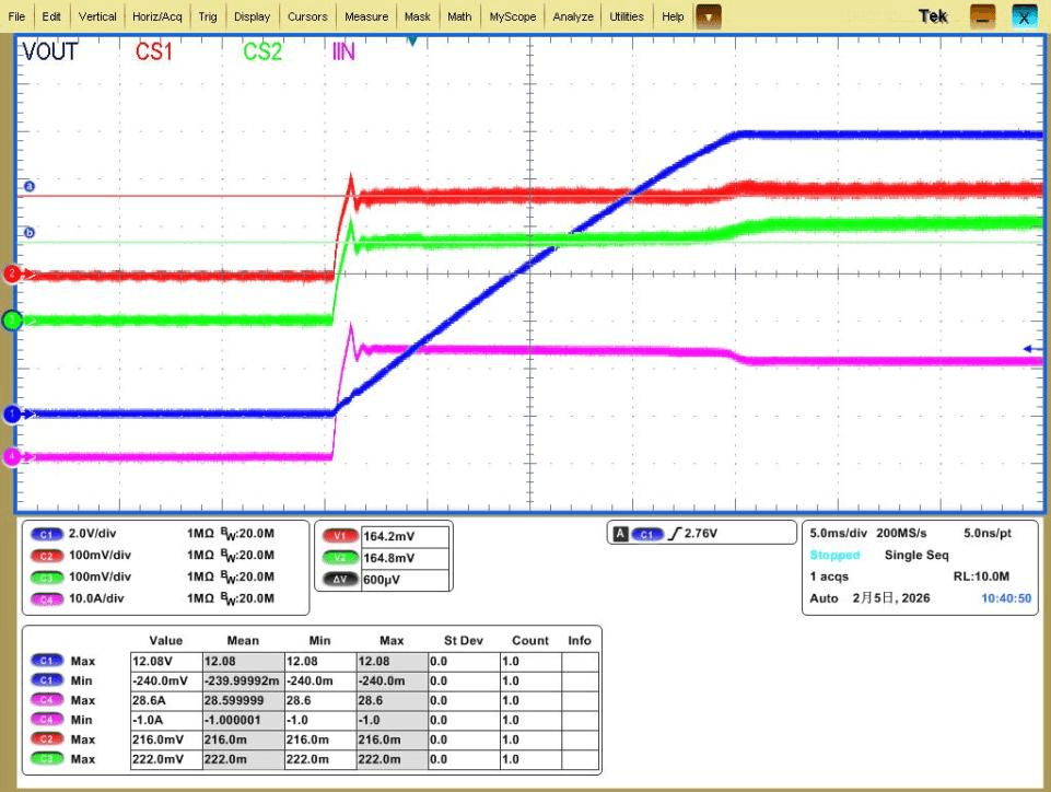
Current Sharing Test with Two Parallel Devices: Startup with a 20A load
-
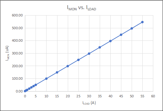
0-55A Imon Accuracy Test: The IS6108B generates a voltage proportional to the device current using an external resistor from the IMON pin to GND, enabling high-precision current monitoring.